OK, on to replacing the third waste valve on our 2015 Voltage Epic 3800.
You can no longer order directly from Valterra, but all of their products are available on Amazon…and for less money!!!
This third valve drains the grey water tank that is connected to the Kitchen and the Garage Bathroom sink.
I got lucky and opened the belly on the left side just a few inches in from the left frame rail and between the front two axles. I make my cuts from front to rear and then cut from rearward end of cut to rearward end of cut. That way cut is a “flap” still connected at the forward end. Thus using black, heavy duty, duct tape the flap will not be pulled down by the air flow under the trailer when traveling.
So this time, as noted, I opened the belly and found myself looking right up at the valve.
Now the bad news. Dutchmen put a 1½” valve to drain this 48 gallon tank. You can see that in this pic:
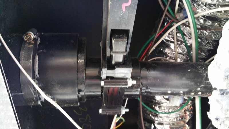
As you can see, looking from left to right, to the left of the clamp is the formed outlet of the tank. There is a fitting over the outlet of the tank and it looks like it was pushed on using Plumbers Putty to seal between the fitting and the tank. Then there is a spigot fitting that reduces 3” to 1½”, Then a spigot fitting flange for the valve. The valve. Then a hub flange fitting, then the 1½” drain piping.
I was able to remove the two lower flange bolts. The top two bolts can’t be removed due to interference with the 3” spigot fitting. So it was necessary pry the 1 ½” drain piping back so that the valve could be valve to be removed. What a poor design an PITA to get out.
Note the Plumbers Putty all over the end of the fitting over the tank outlet. I could not get the fitting off the tank outlet, so out came the Milwaukee 12V Hacksall and I cut the tank outlet right behind the fitting. As you can see there will still be plenty of tank outlet to attach the new valve fitting.
Gads, with the fitting cut off it is obvious that during assembly Dutchmen used ABS cement to put a piece of 3” ABS pipe into the tank outlet nearly all the way into the tank! Now what to do? The outside diameter of the ABS pipe inside the tank outlet measures just under 3 11/16”. So a 3” ABS coupling isn’t going to go over it, with an ID of 3.5”.
So get a 3” ABS coupling, chuck it up in the lathe and cut the ID on one side to just under 3 11/16”. That fits over the tank outlet very nicely and ABS cement will surely seal it. Everyone has a lathe don’t they? Or someone that can do a 5 minute lathe job?
For the new 3” Valterra electric valve I bought these three fittings on Amazon.com
Valterra T1005 3” Slip Hub Flange $6.58
Valterra T1006 3” Spigot Flange $7.04
Valterra T1041-1 Eccentric Tank Reducer with 3” spigot x 1½” Hub $7.39
Now, having put in two Valterra electric valves and how quickly ABS cement sets up…I ordered two of each fitting. So about $40 and free shipping with Amazon Prime.
I glued a 3” spigot flange into the un-machined half of the coupling first. Sure enough, I used lots of cement and used a deadblow hammer to drive the flange fitting into the coupling on the work bench first. But got it on there!!!
Putting a good coat of ABS cement on the inside of the machined coupling it went on the tank outlet smoothly and got the flange in the correct orientation for installing the new valve.
I used ABS cement to glue the Eccentric Tank Reducer into a Slip Hub Flange. And sure enough I was not quick enough and didn’t get the fitting in far enough. So, thankfully I ordered two of each fitting and was more prepared, got it plenty engaged, but not all the way it. Whew that cement sets up fast. And no, I checked there is no other cement for use with ABS fittings that isn’t just as fast setting up!
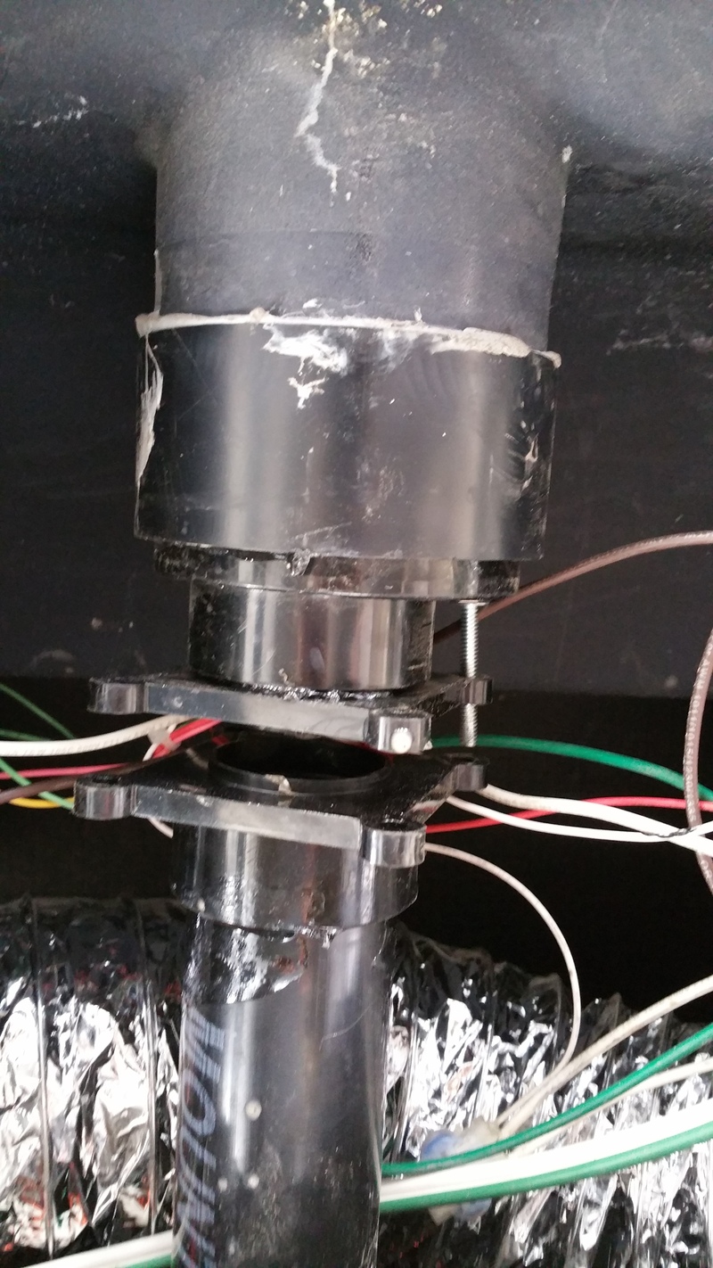
Here is the new valve installed bolted up and ready for wiring. Yeah, there is a real mess of wiring left by Dutchmen. So I used small zip ties and pieces of duct tape to get them gathered up and out of the way.

Wiring the valve for operation:
I mounted the switch in the “wet cabinet” where all the water connections are located. That put the new switch about 12 feet forward of the valve. The Valterra electric valve comes with a 3 ft long, 2 wire, cable for connecting to power and a 7 ft long, 3 wire, cable for connecting the switch to the valve.
The switch to valve cable comes with a plastic connector on the end. And the other end of the connector is at the valve. Here’s what I did: Cut the 3 wire cable a foot back from the plastic connector. Leaving me with a foot long cable and connector.
Located the location of the wet cabinet from underneath and cut a 6”x 6” flap in the belly. Sure enough, can see daylight up to the back of the wet cabinet.
Tried to run a fish tape from there back to where the valve is located. Nope, way too many obstructions. So I cut a 6”x 6” flap in the belly every 24” all the way back to the valve location. That allowed me to get the fish tape run all the way back to the valve opening in the belly. I then cut a 12ft section of green, black and white 16 ga wiring. Matching the wire colors in the 3 wire cable. I use crimp fittings to connect wires in automotive situations as soldering the wires tends to make them brittle and subject to breakage. After connecting the short section of cable and the plastic connector to the three wires I wrap the bundled crimp fittings with a good layer of quality electrical tape. I covered the new wires with ¼” split loom and wrapped the loom with electrical tape every 12 inches.
Use electrical tape to connect the new wires an split loom to the end of the fish tape and pull it forward to the flap cut right under the “wet cabinet”.
I then plugged the two halves of the cable connector together and pulled the wiring forward leaving some slack in the harness at the valve
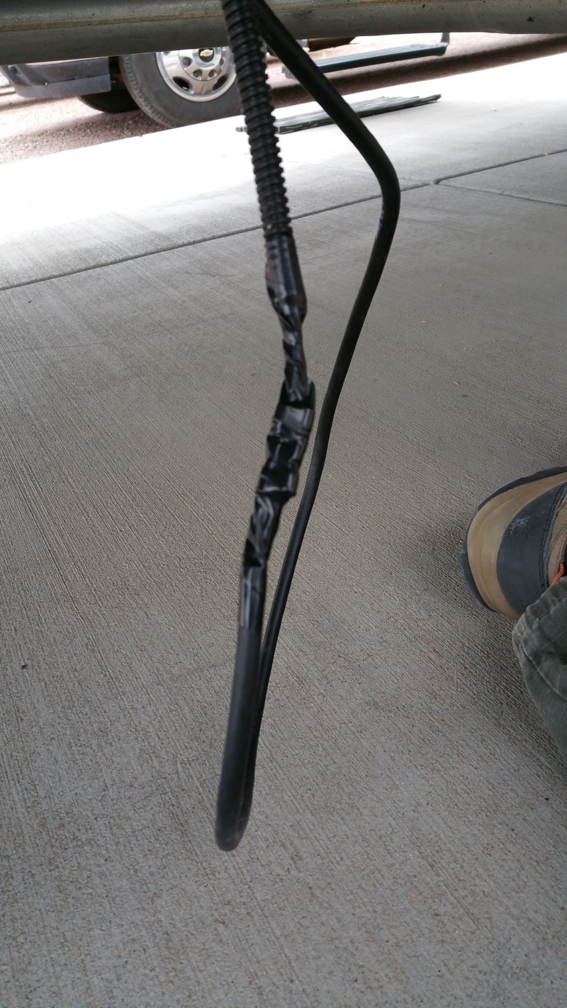
Now I fished the long end of the 3 wire cable down through the PEX piping and out the flap under the wet cabinet.
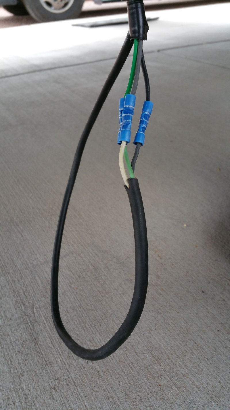
I cut the 3 wire cable and the three new wires pulled forward so that the crimp connection would be just above the belly at the flap under the wet cabinet. Easy to get to in the future if necessary. In this pic you can see the crimp connectors I chose to use. The next pic shows the connection covered with electrical tape for protection.
Here’s a pic of the inside of my wet cabinet showing the location of the three electric valve switches. Note at the top of the cabinet is a light fixture. I tied the power leads for all three switches to the power leads to that light fixture. Thus there is always power to the valves.
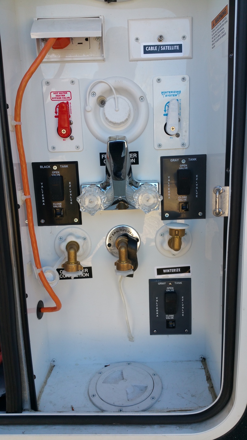
First off, the weird faucet? The original faucet with the quick connect outdoor shower hose froze and split the cold water connection. I just haven’t gotten around to ordering a replacement and this $9 faucet from Home Depot is hanging in there.
The orange cord? It goes through the wet cabinet wall and into the “basement” and provides power to the pancake air compressor mounted there.
The new valve switch is at the lower right in the cabinet.
The switch installation calls for cutting two holes in the mounting surface, in my case the sheet metal covered ½” OSB that makes up the wet cabinet. How does one do that?
Well, each Valterra valve comes with a switch plate for “grey water” and one for “black water”. So you can use one for a template without worrying about messing it up…just use the correct one…the one that does not apply to the valve application!!!
I took blue masking tape and taped the “black water” switch plate to the inside of the wet cabinet in the correct location. I then drilled the three screw locations with a 3/32” drill bit. Now went ahead and put the three screws in so the switch plate was held in place correctly. I now took the sharpie and traced the inside of each rectangular hole in the switch plate.
Now remove the screws and switch plate. I used a 3” cut off wheel on a 90 degree die-grinder to cut the sheet metal. One could use abrasive cut off wheels on a Dremel tool just as well. I did make my cuts just outside the sharpie lines to make sure the holes would be just a bit oversize. With the sheet metal out of the way…I drilled a 3/8” hole in the OSB to give me a starting place, then used my RotoZip saw to cut the OSB rectangles out. Now everything is prepped for installation of the switch following the instructions.
With the valve installed and wired up, time to test. I crawled under the Voltage to observe when “she who must be obeyed” flipped the switch. Tested several times and works like a charm!
Used the heavy duty black duct tape to close up all the “flaps” cut in the belly material, pitched all the left over debris, kept the 1½” manual valve, put away all the tools…and DONE!!! No more crawling in the gravel or the mud or the ? to get to the manual handle!! Just flip the switch and good to go!!!
Oh, and be aware, when you cut the fitting on the tank outlet…there is going to be some nastly stuff dripping out. Why? Well you mount a 1½” valve in the center of a 3½” outlet…and the tank isn’t going to completely drain. What’s left is sort of congealed whatever went down the kitchen sink. YUK!!!
If you would like a copy of the Word document I created this post from, send me a PM and your e-mail address and I'll send it along.
That's all there was to it!!
Pirate


 Linear Mode


